- label Explenation
- favorite 2 likes
- remove_red_eye 7266 views
- comment 0 comments
The DC-Car decoders have a large number of parameters that can be CVs are adjustable. CV stands for Configurable Variables, these are settings that affect the functioning of the decoder. You should think of:
- Addressing: the DCC address of the decoder
- Maximum / minimum speed
- Driving positions / speed table
- Flashing frequency of turn signals, flashing lights and strobes
- Braking and acceleration possibilities of the anti-collision system
- Continuous lighting
- Automatic functions
- Vehicle type
- Polarity of the light outputs
- etc.
You will find the latest English CV list on the download page.
Programming CVs can be done in two ways:
- Via a DCC control panel that has a main track programming mode (POM).
- Using the CV Programmer and a PC with the free CV software.
Programming via a DCC Center.
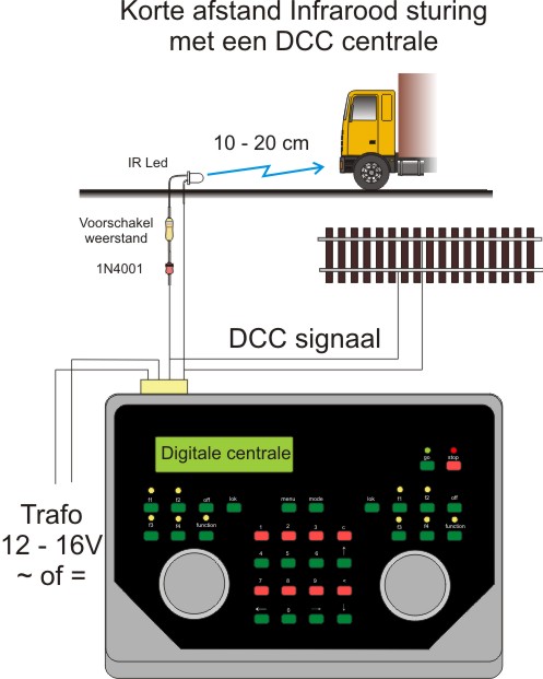
Programming CVs via a DCC Central is possible if the central has main track programming. The decoders cannot be the programming track. The required components only consist of a resistor, a diode and an IR LED. Because communication is unidirectional, variables can only be written and not read out! The following panels have been tested: • Intellibox (Main track programming available) • Lenz (Main track programming available) • PIKO Digi1 (No programming possible) • ROCO Lokmuis (No programming possible) • TAMS EasyControl (Main track programming available) • Zimo....
The connection diagram for a DCC control panel is the same as for short-range infrared control and looks as shown below:
The CV-Programmer:
Much more convenient is programming via the CV-Programmer. Two-way communication with the decoder is possible, so that in addition to writing values, we can also read them back from the decoder.
The image below shows the CV-Programmer.

How it works: The DC-Car car is connected via the 8-pole update connector connected to the CV-Programmer which in itself is connected to a PC. This connection is standard via the USB port. By means of the free CV-Programmer software makes the decoder easy and clear to program. The CV values can be saved, copied and loaded per vehicle. The software is multi language!
The CVs
The most frequently used CVs from the CV list can be found below with an explanation of what is for and how it can be set. This list is by no means exhaustive, it is almost impossible to describe the more than 135 CVs in such detail. The CV Programmer software is a solution for this because it indicates per CV which values can be programmed and what the different values do.
1 Programmable address from 1 to 9999 (CV 1, 3, 15, 16, 17, 18 and CV 29)
1.1 Program the first short or long address
Each car can be controlled separately via DCC commands that are generated, for example, by an Intellibox or another DCC center. Just like with the DCC train control, every car gets its own address. This can be a so-called short address (1 - 127), but it can also be long (128 - 9999). The choice for short or long is specified in CV 29. A value 0 makes the choice for short address by means of CV 1. At a value of 32, the choice was made for long addresses by means of CV 17 and CV 18. Precondition: the value in CV 1 must not be the same as that of CV 3 In addition, there is a possibility to add a second short address CV 3 (1 - 127) and a second long address CV 15 and CV 16 (128 - 9999) to program and use. Precondition: the value in CV 3 must not be the same as that in CV 1 The following options are available when programming addresses: New short address, if a short address has been used up to now: Loc address = Current short decoder address (1-127) CV = 1 Value = New short address 1-127 New long address, if a short address has been used so far: Loc address = Current short decoder address (1 - 127) CV = 17 Value = New long address high part Lok address = Current short decoder address (1 - 127) CV = 18 Value = New long address low part Lok address = Current short decoder address (1 - 127) CV = 29 Value = 32 New short address a long address has previously been used: Loc address = Current long decoder address (128 - 9999) CV = 1 Value = New short address 1-127 Loc address = Current long decoder address (128 - 9999) CV = 29 Value = 0 New long address, if a long address has been used up to now: In this case, the decoder must first be used Short address can be set, otherwise it may no longer be possible to program it! Set to a short address first (example = address 1): Loc address = Current long decoder address (128 - 9999) CV = 1 Value = 1 Loc address = Current long decoder address (128 - 9999) CV = 29 Value = 0 Now the new long address can be programmed: Loc address = Current short decoder Address (1 - 127) CV = 17 Value = New long address high part Lok address = Current short decoder address (1 - 127) CV = 18 Value = New long address low part Lok address = Current short decoder address (1 - 127) 127) CV = 29 Value = 32 Note: Many Digital exchanges have a special facility to program long addresses. Calculation of the values for CV17 and CV18: The long addresses run from 128 - 9999. If an address is greater than 127 and less than 256, CV17 is programmed to "0" and CV 18 to the corresponding address. If the address is greater than 255, the following calculation must be made for the values of CV 17 and CV 18: Divide the address by 256. The value of the whole number comes in CV17. Then 256 is multiplied by the values in CV17 and the result of CV17 subtracted. The outcome comes in CV18. As an example the calculation of address 130: The address 130 is smaller as 256 CV17 = 0 and CV 18 = 130 CV29 = 32 As an example the calculation of address 500: 500: 256 = 1.95 ... The part after the decimal point is not used 256 X 1 = 256 500 - 256 = 244 CV17 = 1 and CV 18 = 244
1.2 Program the second short or long address
Will become possible in the future
2 Programmable starting speed (CV2)
Because the cars have different constructions and a range of engines is possible, there will be different driving behavior. To get a nice driving behavior, the driving characteristics can therefore be adjusted and coordinated with each other via CVs. One of those differences is the moment when a car starts moving. With CV 2 a value can be set here to start the car in driving position 1. Driving position 28 (the maximum speed) remains unchanged, however all intermediate driving positions are automatically recalculated so that the speed change remains more or less constant with each driving position. CV 2 is factory-set to 45, the range is from 3 to 152. Precondition: the value must be at least 28 less than that of CV 5
3 Programmable maximum speed (CV 5)
In addition to the starting speed, the maximum speed can also be programmed. This is therefore the speed at driving position 28 and is entered at CV 5. Driving position 1 (the initial speed) remains unchanged, however, all intermediate driving positions are automatically recalculated so that the speed change remains more or less constant with each driving position. CV 5 is factory-set to 180, the range from 31 to 180. Precondition: the value must be at least 28 higher than that of CV 5
4 Programmable speed curve (CV 70 - CV 97)
The decoder works with 28 driving modes. A desired speed can be programmed for each driving position in CV 70 –CV 97. In this way, a speed curve for the car can be established. In CV 70 the speed for driving position 28 is entered. In the following CV the speed for driving position 27, etc.
5 Option to control 2 servos (CV 11 - CV 14)
Will become possible in the future
6 Support of InfraCar functions (CV 19)
The decoders also support the InfraCar system. CV 19 allows you to set the properties of the F4 function. The value 0 causes F4 to switch light 2 in Infracar mode. The value 1 activates and deactivates the reed switch for F4 in Infracar mode.
7 function outputs for e.g. beacon, strobes, rear fog light, etc., etc. (CV 24, CV 20)
With the decoders for trains, F0 is used for lighting. This is also the case with the DC04 decoder. F0 switches the lighting at the front and rear. In addition, the various vehicles such as emergency services, trucks, buses, etc. have special lighting. In order to get the most realistic representation of reality, a large number of control options for flashing lights, flash, swell lights, etc. are provided.
7.1 Lighting in general:
You can set which lamps should be on after switching on the vehicle with CV 24.The following values are possible: 0 = No lighting, 1 = Left flashing light always on 2 = Right flashing light always on 3 = Warning lighting on 4 = Light 2 always on 8 = Light 3 always on (depending on CV20) 16 = Light 4 always on (depending on CV20) 32 = Flashing lights always on 64 = Front flash units always on 128 = Lighting always on
7.2 Multi Functional outputs:
CV 20 controls the assignment of the function keys for controlling the Multi Functional outputs MF1 and MF2 for use with blue beacons. The values in CV 20 have the following functions: 0 = MF1 is used as light 3 MF2 is used as light 4 Light 4 is switched at the same time as light 3 1 = MF1 is used as light 3 MF2 is used as Servo output 1 2 = MF1 is going to be if Servo output 2 is used MF2 is used as Servo output 1 3 = MF1 is used as Servo output 2 MF2 is used as Servo output 1 4 = Trailer available 8 = Reserved 16 = Light 4 as swell light (only switched at the same time as the front flash ) 32 = The time units in CV33, CV35, CV37 and CV138 or CV126, CV129, CV132 and CV135 are not used. The time units are determined randomly 64 = Reserved 128 = Reserved Timing for the flashing light: It is possible to change the swing frequencies of the flashing lights. With this setting you are therefore able to realize realistic representation of several flashing lights at the same time, in reality the rotating light does not all turn exactly the same. The setting is as follows: With CV 34 you can set the time that flashing light 1 is on. This value can be between 1 - 254. A value 0 turns off the beacon while a value 255 turns the beacon on continuously. The lights can also be switched on or off via the function keys on the Digital Central or the function blocks. This keeps the extra light outputs free for special lighting such as spotlights, etc. With CV 35 you determine the time when rotating beacon 1 is off. This value may be between 1 - 254. Note CV 34 and CV 35 may not have the same value! For rotating beacons 2, use CV 36, CV 37. The setting of the values is the same as for rotating beacon 1. Note CV 36 and CV 37 must not have the same value! For rotating beacons 3 use CV 32, CV 33. The setting of the values is the same as for rotating beacon 1. Note CV 32 and CV 33 must not have the same value! Timing for the flashes: It is also possible to change the flash frequencies of the flashes. With this setting you are therefore able to realize realistic displays of multiple flash units at the same time, in reality not all of them flash exactly the same. The setting is as follows: With CV 38 you can set the time that the front flash is on. This value can be between 1 - 254. A value of 255 flashes the flash continuously. With CV 39 you determine the time that the flash is off. This value can be between 1 - 254. The lights can also be switched on or off via the function keys on the Digital Central or the function blocks. This keeps the additional light outputs free for special lighting such as spotlights, etc. CV38, CV39, CV40 and CV41 must not have the same values! For the 2nd flash use CV 40, CV 41. The setting of the values is the same as for flash 1. CV38, CV39, CV40 and CV41 must not have the same values!
7.3 Direction indicators:
There is even an option for setting the flashing frequency of the turn signals and that also separate for left and right. The turn signal can also be permanently on to simulate a defective indicator. For the left turn signal, the settings are made in CV 30. CV 31 is used for the right turn signal. The values can be chosen from 1 to 254. A value of 0 leaves the turn signal permanently on.
8 Automatically switchable lighting (CV 42, CV 43, CV 44 and CV 45)
There is an option to connect a light sensor. This makes it possible to switch the main lighting on and off automatically depending on the ambient light. To get a realistic representation of reality, the moment of switching on or off has also been made programmable. This is as follows. CV 42 and CV 43 determine when the light goes out. The formula for this is (CV 42 * 256) * CV 43. CV 44 and CV 45 determine when the light comes on. The formula for this is (CV 44 * 256) * CV 45.
Comments (0)