- label Product
- favorite 0 likes
- remove_red_eye 3825 views
- comment 0 comments
A bit of history:
Why was the DC-Car Booster developed? A number of users find it (too) much work to mount a large number of LEDs along the side of the road (short range IR control), so that the cars can be controlled by a digital DCC station. Claus Ilchmann had been thinking for some time about a possibility of sending the DCC commands to the cars via a kind of remote control. Until recently, the possibilities were limited due to the speed of data transfer or the too short bridging distance. Until some time a suitable receiver was found in the form of the LCIR. This turned out to be the ideal receiver for the cars to receive the DCC protocol directly via infrared transmitters.
Now only an infrared Booster had to be developed with which it would be possible to control sufficient infrared LEDs. Those LEDs are mounted above the layout so that the cars can receive the signal everywhere. Instead of many LEDs along the side of the road, only a few LEDs are needed above the layout. The range is no longer a problem as the Booster does its work up to a distance of 5 meters. If there are reception problems in certain locations, LEDs can also be installed along the side of the road or an LED from the booster can be mounted directly above this location.
The short-range infrared LEDs are turned on by means of a diode and a resistor connected to the rails connection of the digital central. The cars respond to both long-range infrared LEDs, short-range LEDs and function blocks. A mix of all possible infrared controls is therefore possible.
What is needed in a car to receive the long-range infrared?
The DC-Car Booster only works with the DC04 decoders (software version from April 2008) for this purpose the optional TSOP7000 receiver must be connected to the serial input of the DC04.
Value 4 must be programmed in CV21.
What else is needed for the DC-Car Booster?
12-16 Volt AC voltage.
A digital exchange that works with the DCC protocol.
The infrared LEDs:
All 7 outputs can be loaded up to 1 Ampere in total.
An infrared LED or a chain of max. 5 infrared LEDs can be connected to each output.
The ballast resistors (2 Watt) can be calculated according to the LEDs to be used.
You can use the following values for this:
1 LED: with 220 OHM
5 LEDs in 'series: with 100 OHM
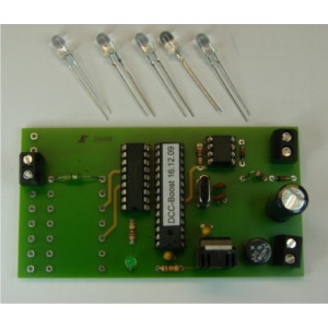
The DC-Car Booster is simply connected to the rails output of the digital center.
Operation:
The red LED has a control function. When a DCC signal is present it lights up.
The resistors R4-R8 are 2 Watt and are the ballast resistors for the infrared LEDs
The value can be determined experimentally and depends on the infrared LEDs used
Example:
With an LED that can be loaded with 100mA, the resistance is 220 Ohm.
With a chain of 5 LEDs, the resistance becomes 100 Ohm.
Any infrared LED with a wavelength of 870-890nm can be used as a transmitter LED. With LEDs with a wavelength of 940nm, the range is reduced by half.
For the best range, we recommend the LEDs from our webshop. You will also find the kit of the DC-Car Booster there.
Comments (0)